Nissan 240SX Forums banner
Status
Not open for further replies.
61 - 80 of 143 Posts
i dont know how the whole process works, but it looks like the machine to do the milling was set on too fast of a speed, because i know that is how brake drums and rotors look if the lathe is set on too high of a speed(kind of spiraled), i dunno that is what it looks like to me.
 
Discussion starter · #63 ·
Ready to go

Well guys i got the head back and i must say i am now satisfied and ready to continue along with the project! The shop that did my head the first time wasnt exactly a "performance" shop, more of just a "rebuild" shop so they wont take the measures that a performance shop would.

Last time i posted, the head had scratches and didnt look good enough for the Cometic MLS headgasket i was planning on using. Some of the scratches you could literally feel with a sharp finger nail! I took it back to my favorite machinist, Precision Engine Rebuilders, and they told me that it wasnt too bad and that i wouldnt run into any problems with the type of headgasket i wanted to use. The owner told me this and he also said that as long as there wasnt any deep scratches running across the fire rings, id be ok. But since there was a deep scratch that would've possed a threat, i decided to have the head milled once again. While they were at that, the filled down any sharp edges formed from the milling process. They also had to remove the cams so all the valves could close. From the pictures provided you will be able to see the paint that has come off from the valves from the previouse shop.

Let this be a lesson to me and all the future CA tuners that follow! Make sure you have critical and very important machining done by a reputable, experienced, and equiped machinist! If not, you'll end up paying twice like i did! Learn from others' mistakes so you wont have to repeat them!

Image


Image


Image


Luckily this little detour only cost me $60.00. Phew! :bigthumb Heres my head as of now. Just waiting for that Cometic head gasket to arrive (1.55mm). The mating surface shines just like in the pictures. I know that its not that obvious in the pictures but in real life and up close its Amazing!

Image


Image


Image


Image


Image


Image


Image
 
Discussion starter · #69 ·
I want More
Oh you'll get more, i gurantee it! Im waiting on a Nismo Fuel Pressure Regulator, and poweder coated engine covers. Ill make sure to post pictures of it asap. Any recommendations on an exhaust system? Price and quality are important.
 
Discussion starter · #70 · (Edited)
Update: Feb 24 2007

Good news! I finally put the head and block together. Got a few things torqued down and next week hopefully ill have my freshly powdercoated covers! I got my Cometic HG(1.55mm), ARP sr20 main stud kit, timing belt, timing belt component kit and a bunch of other little odds and ends.

Before reassembly.
Image


Theres my block, head, and other parts that will soon go on. There's my school's shop where ill be finishing my project.
Image


Prepping the block.
Image


Heres the block ready for the headgasket. As a reminder the block had much done to it, those are CP pistons 8.5:1 CR, balanced assembly, honed walls, decked, and new bearings. I wish i couldve changed the rod bolts but we'll start with this for now. New seals, gaskets, bearings and paint to freshen-up the bottom end.
Image


So fresh and so clean! New water pump from a rwd ca18et, new oil pump from the fwd ca18de, and timing components. The transformation begins. :bowdown
Image


Quick comparison of the oem Nissan gasket and the Cometic gasket. It'll be good to see how it goes. (i know one is upside down and the other down side up, if that makes sense)
Image


Headgasket goes on. Watch out for that Moly Lube!
Image


I love the way everything looks so shiny and clean. I love new parts.
Image


Take a close look in there!
Image


Another nice detailed shot. This time i wasnt using my camera because i lost my battery. The is a 7MP Sony Cybershot and it performs way better than my Konica Minolta 5MP Dimage x50. Ill try and use it again later.
Image


And another one...
Image


There i am putting the cylinder head on. I highly recommend you put the ARP washers in before you put the head back on! I tried both ways and the only way i could get it to work was if i dropped the washers in there firsts, all eight, then set the head down. If you try putting the washers in after you set the head down, there wont be enough room for them to go through. Be aware and use what ever works but this is what worked for me!
Image


If only i knew how to use macro mode on this camera. Heres the gasket all squeezed up.
Image


Damn blurry photos.
Image


Here we go! That gasket looks mighty thick compared to the oem unit buts its that way for a reason. Since i had the block and head machined the extra thickness is for compensation, nothing else!
Image


There i am again torque-ing everything down to spec. ARP instructions said to torque it down to 70 ft lbs using their specially formulated Moly Grease. The FSM says 76 ft lbs. I did 72ft lbs because i had to use a few adapters. Get a load of my sweet yellow safety glasses! :pface
Image


Finished. Next are the covers, plates, fuel rail which will be powdercoated.
Image


As of now, how much was all this you ask?

pressure wash block - $90.00
deglaze hone 4 cyl (upto .030) - $90.00
deck straight block - $100.00
balance crankshaft (internal) - $160.00
change pistons (4 cyl set) - $58.00
standard short block assembly - $325.00
tear down short block - $40.00
rod bearings (clevite) - $31.88
main bearings (clevite) - $49.95
sales tax - $5.32
freight - $13.57

TOTAL - $963.72

CP Pistons (pistons, rings, pins, clips, and shipping) - $570.34

TOTAL w/ pistons - $1534.06

Nissan OEM gasket kit 10101-CA18 - $236.34
CA18DE Oil Pump - $ 101.49
Crankshaft gear - $23.05
Crank plate 13022-42L00 (behind crankgear) - $2.78
CA18ET Water Pump - $43.49
CA18DET Alluminum pulley kit (alternator, water pump, PS pump) - $80.00
Bead/Sand Blasting Valve Covers, Timing Covers $30.00
Cylinder Head (3-angle valve job, milled, exhaust valve, misc fee) - $241.00
ARP SR20 Main Stud Kit 202-5402 (head stud kit) - $82.84
Timing belt component kit - $88.97
Timing Belt (Gates/Napa) - $19.92
Camshaft Rear Seals (half moon shaped) - $6.95
Cylinder Head (Mill and wash Head again due to crappy 1st shop) - $60.00
Cometic MLS Headgasket (1.55mm) - $127.65

TOTAL (so far) - $1144.48

TOTAL w/ previous total - $2678.54

:ahh Yup thats a lot of money and its not yet finished! Ill update with more goodness as soon as they become available.
 
David your CA is looking quite sweet. I'm glad to see someone doing it right the first time. I noticed that you picked up a set of CA pulleys. I picked up a similar set from Drift Factory and had fitment issues with them. On my set the water pump pulley didn't line up correctly with the crank, and the PS pulley had a completely different pattern in the center for mounting. Have you already checked yours for similar problems? Asking cause I noticed you picked them up from a forum member and didn't want too much time to pass you by in case you needed to return them or something.

Wei
 
Discussion starter · #73 ·
David your CA is looking quite sweet. I'm glad to see someone doing it right the first time. I noticed that you picked up a set of CA pulleys. I picked up a similar set from Drift Factory and had fitment issues with them. On my set the water pump pulley didn't line up correctly with the crank, and the PS pulley had a completely different pattern in the center for mounting. Have you already checked yours for similar problems? Asking cause I noticed you picked them up from a forum member and didn't want too much time to pass you by in case you needed to return them or something.

Wei
Thanks dude!

I havent even put the pullies on yet. The waterpump one is the same. I dont know about the PS and Alternator but im pretty sure theyre the same. Ill let you know when i get to it. Well actually i did get them from a forum member and i bought them a long time ago. Few months maybe.
 
Discussion starter · #77 ·
Project Progress: March 28 2007


Yes! Here you go!

Check it out guys...

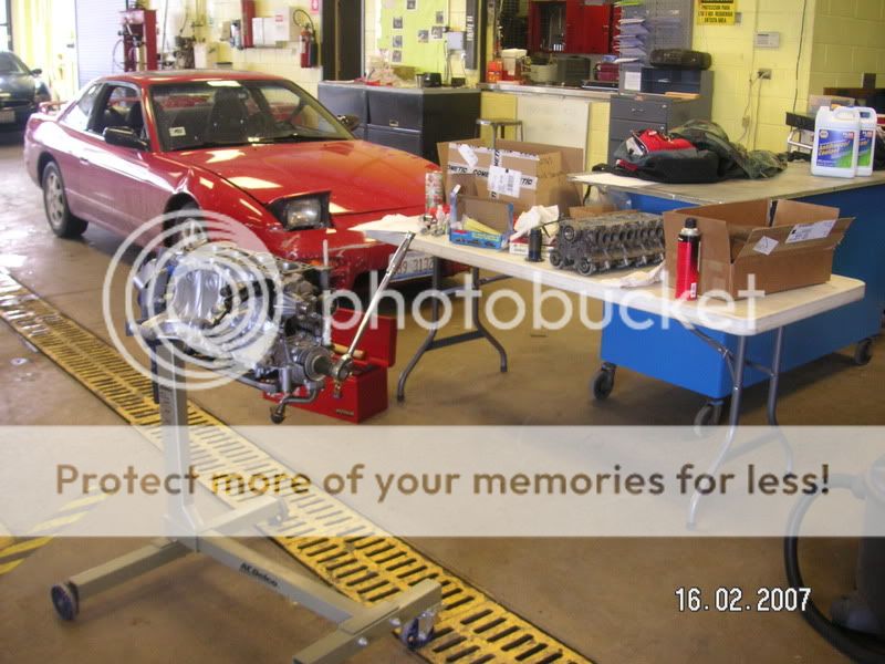
I havent posted in a while but its because ive been working on the engine and taking pictures of the progress. Heres some pictures of what ive been currrently doing. This past week ive been going to my school and getting as much as possible done as the deadline draws near. Im still missing a few things here and there like the exhaust system, intercooler system, and other miscellaneous parts. So far ive just been putting back together what i have available and still waiting on my cam covers aswell. Im also still waiting on my income tax return refund and some paycheck money. Once i have this money, im buying some more things. :bigthumb


Rear cam gear plate goes on. Line it up and bolt it down! Install the tensioner and spring afterwards. Torque down the idler pulley if you havent done so already. Make sure you torque down everything according to OEM specifications!
Image


Using a correct size allen wrench/key to rotate the tensioner in a way so that the timing belt can go on. Remember to set number one piston to top dead center and line up the marks on the crank and cam gears with their corresponding marks on the oil pump and rear cover plate.
Image


Here it is installed! Make sure everthing is lined up correctly and nothing hits, like piston to valves.
Image


Thats it!
Image


Heres a nice black and white. :gapteeth
Image


Picasa picture editing program to the rescue! Install lower timing belt cover.
Image


Install the cam gear cover.
Image


Heres a shot with the cam gear/timing belt covers back on. These were powder coated "Little Wagon Red."
Image


Some more photo editing by me.
Image


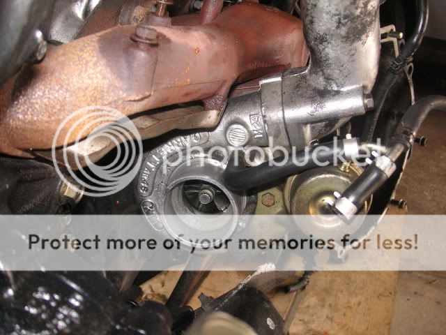
Heres a test fit of the remainder of the intake manifold. I also test fit the exhuast manifold and rebuilt CA t25 tubro. When installing the Crank/Cam Angle Sensor line up the spline in the camshaft with the shaft on the sensor. Do not force anything as it has become a common thing for this to break off! I dont know how you can break it off as it isnt rocket science but just ease it in, nice and slow. Finger tighten your three bolts that hold it to the cam cover and leave them loose incase you need to adjust timing later. :uhhuh
Image


Black and white of the test fitting.
Image


And i cant think of a better caption for this one.
Image


Nismo adjustable Fuel Pressure Regulator and my nicely redone fuel rail. Replaced the phillips style bolts with hex head because of less chance of stripping the bolt. Looks better this way.
Image


Here i cleaned up the area in and around the thermostat housing. We still need the coolant temp sensors.
Image


New thermostat and gasket...
Image


Torque down the three bolts and youre done!
Image


Rear collector cover for the intake manifold. This is so i have something of how the hoses were origanally.
Image


Looking more complete! I still need to install the injectors and fuel rail. Hoses and lines are next.
Image


Remember to install the coolant temp sensors as shown. I like taking lots of pictures! :biggrin
Image


Heres a good shot of the powedercoated manifold. Its not the greatest but it sure looks really nice in the red. The whole scheme came out pretty damn good towards the end.
Image


This ones a little easier to see.
Image


A performance rebuilt CA18DET, $2600.00+ and counting... The day i get it running, priceless. :ylsuper
Image


Incase i didnt mention it earlier, the oil pan is installed using Nissan RTV type sealant and new front and rear seals.
Image


A closer look...
Image


and another...
Image


I installed the throttle body and tested the TPS but couldnt verify if it is truely working correctly. There was a break in the signal when testing with a DVOM but i havent tested it with a Digital Osiliscope so i cant deem it worthless just yet. I am going to go buy a new TPS and compare the new one to my old one.
Image


Im soon coming up on a year since i got this engine and its not yet complete. By the end of the month, April, i plan on having it done. Im glad ill be getting help from others, teachers, and the school shop for this one.
Image


:naughty Nice!
Image


Heres the exhaust side without a manifold yet. Im currently shopping around for an aftermarket manifold and ive almost narrowed it down. Its most than likely going to be an "Ebay" manifold. I think im going with a Megan Racing turbo outlet and flex downpipe. Any ideas?
Image


Cornered away...
Image


Now theres a good side shot. Fuel rail, injectors, seals, and o-rings all installed.
Image


Heres a good look at the Butterfly Vacuum Actuator and Nismo Adj Fuel Regulator. I tested the vacuum pot and it held vacuum so i can assume it is still in good condition. I also replaced the phillips type bolts with hex head style for increased strength. These little suckers dont like to come out when they've been sitting in there for years and years.
Image


Heres the original 370cc injectors that came with my motorset. I did a resistance check, replaced the o-rings, replaced the other rubber grommet, and made sure they were clean from any obstructions or clogs. I could have had them sent out to have them further tested and balance test, etc. but i didnt think i should be too worried as these arent that expensive to replace. Before i put them into the fuel rail, i made sure there was no debris inside and put a little bit of oil on the o-rings to ease them in.
Image


Stock fuel system will do, for now.
Image


Theres my rebuilt CA T25 and manifold. I rebuilt it myself using common tools and instructions i found online. Before this, i had never done this so it'll be good to see what happens. If it all blows and fails, well i wont feel so bad as it didnt cost me much and it was a great learning experience. I made marks and lined up the compressor wheel and turbine wheel so i think ill be ok. Ive heard that these things were balanced by Garrett individually piece by piece or as an assembly. Im just hoping to get a few thousand miles out of it and then comes an upgrade. Ill post any news if anything happens.
Image


Dont you just love that freshly rebuilt engine smell...
Image


Backside view of the exhaust housing and turbine wheel. Plans for the turbo are Taka SS lines and Megan Racing Outlet and Downpipe.
Image


Rear top view...
Image


Front view...
Image


Another rear-end view?!
Image


Sub-manifold and misc accesories...
Image


Sometimes i take tooooo many pictures... :pface
Image


Heres a shot of the cleaned up mating surface for the idle control devices. On the bottom left you can see a part of the idle control valves all cleaned up and ready to go. I also tested the valves/devices according to the FSM and made sure they are within specs. I disassembled the valves and made sure the moving pistons/peices inside were free to move and not sticking. Hopefully this will eliminate any future problems related to idle and warm up.
Image


New gaskets and free moving parts. Those little pistons at the bottom left came from the Auxiliary Air Control valve.
Image


A close up of you know what...
Image


If youre thinking, where the hell are his cam covers, well heres what happened. When i went to pick up all the pieces that i got powdercoated, i looked at the cam covers and refused to use them the way the company left them. The coating was bubbling and flaking off, especially at the flat mating surface where the "ornament" cover goes (c.o.p. cover). They also bubbled up on the top of the covers and were very noticeable. For what i paid, i didnt expect THAT from them. I took them back, talked to the powdercoater, and he agreed he would go back and try again to get them smoother and looking better. I'll post pics later when i get them back.
Image


Side view of motor and manifold setup.
Image


Would there be a risk in not putting back the brackets that come originally on the engine? Has anyone done this(im sure someone has)? Any experience with this?
Image


Some picture i took for some reason i do not remember. I think it was just to show off the red manifold.
Image


There the Idle Air Adjusting Unit, it includes the AAC and FCID.
Image


Under construction...


Modified by davidricardo86 at 6:08 PM 3/29/2007
 
Discussion starter · #78 ·
I take a lot of pictures but i do it because i like to. The way i see it is that others can later use the pictures and the information as a guide or walk-through. Im obviously not going to do a step-by-step of everything but just enough to point you in the right direction. This is my way of contributing and giving back to the CA community. I hope you guys can enjoy this thread as much as i have had trying to get this project together and almost finished.

:gaylaugh
 
Discussion starter · #79 ·
Project Progress: April 9 2007

CA T25 Rebuild:

Also heres some pictures of my ca t25 rebuild. Its a pretty cool to know how these little guys work! It was actually a really straight forward job. Follow the instructions, get the right tools, and just give it a shot. My goal of this job was to rebuild a turbocharger using new seals and bearings from a service kit.

Heres some shots of what the turbo looked like when i got the engine. My first impression was that its really small and i wasnt sure if it was in "good" condition. I know you are suppose to measure shaft axial play to check for wear and tear on the internals. It didnt move too much but i never bothered to use a dial indicator although i should've.
Image


I let the turbo sit around for a while and oil would come out this side if i left the compressor side facing down. My guess was that the seals were bad.
Image


There it is on the longblock with most things still bolted in place.
Image


I put tape on there so the oil wouldnt drip on the floor. Oil coming out of the compressor or exhaust side doesnt sound too good to me. A rebuild is definately in order.
Image


Heres a few things youre going to need to do this. Ill try and list prices and where you can find these things.

Socket and wrench sets. Basic tools.

T25/28 Rebuild kit with dynamic seal (my choice) $72.85 off http://www.ebay.com
Image


Make sure you've got everything you need!
Image


Snap ring pliers
Image


Some motor oil
Image


Instructions or guide. Here is the best one i found http://photo.platonoff.com/Aut...uild/!
Image


Heres the turbo all apart. I didnt get a chance to take pictures of the dissembly but its easier to take something apart rather than to put it back together. Anyways i did get pictures of the build up so you could back track aswell.

Here are the major pieces that make up the turbo. I cleaned everything up in a solvent tank and a wire brush! Looks way better now. :bigthumb
Image


Heres my Dremel i used to clean up the area where the CHRA and the exhaust housing meet. Mine rusted a bit and i had to use a torch and rubber mallet to take it apart. It finally came apart and then i decided id clean this up and remove the rust. I then put a little bit of anti-seize on here to prevent this later.
Image


Aluminum compressor housing...
Image


Compressor housing...
Image


And again. I never knew thats what they looked like on the inside. Pretty cool! :pface
Image


Compressor and turbine wheels with center shaft and all seals and bushings/bearings. I made two reference marks, one on each side as to not throw the balance off. I've heard that Garret balances these from the factory in two ways. One way is with all the rotating pieces seperately, or the other way is all together as one assembly. Ive also heard of people hacing turbos rebalanced after all rebuilds not just when changing wheels. Im not 100% sure so i just made referrence marks and hope that this will be enough. If it all fails well then i learned something atleast. Ill see what happens.
Image


Compressor wheel.
Image


Turbine wheel! Oooh carbon and soot build up.
Image


Heres a good high resolution shot of the compressor wheel! Its pretty cool how you can see the two impellers/blades. It feels very lightweight and really fragile, i wouldnt drop it.
Image


Turbo ID.
Image


Garrett ID numbers.
Image


CHRA ID plate.
Image


Heres what came out of the turbo. There plenty of small pieces so make sure youre organized and keep track of everything and the way it goes.
Image


CHRA internals. These will be changed and freshened up. New seals and bearings.
Image


There are two types of bearings, use the correct ones!
Image


Heres the old seals and what i thought was a retainer type clip.
Image


You can see the old seal there.
Image


New seal is put on.
Image


Next install the washers and retainer clips.
Image


Think about this one here. Look at the way the clip is shaped and the way it is able to be moved.
Image


Open it up and rotate it on.
Image


This is what yours should look like!
Image


Install this c-clip with a small enough internal snap ring plier.
Image


It fits inside the CHRA in a cut out. It will just snap right into place and it what holds the bearings from moving.
Image


Get the first bearing and put it in your oil.
Image


Put it into the turbine side.
Image


This washer follows the turbine side bearing.
Image


Put the other bearing in oil.
Image


Insert it into the compressor side.
Image


Next prepare the thrust bearing and and collar and install that seal("C") on the bearing part.
Image


Here it is installed on the bearing. Use some thing like snap ring pliers to pry the end open enough.
Image


Put the parts into oil.
Image


Install the thrust bearing and collar the correct way. Pay attention to the desgin of the metal and the way it was originally.
Image


This is how it is suppose to be.
Image


Next find the three bolts that hold the collar and bearing in place. They are very small and do not require a lot of torque. It appears that they even come with a type of "loc-tite."
Image


Use a T-15 Torx bit to tighten.
Image


Tighten the bolts.
Image


Next grab the dynamic seal plate, the rubber seal, and the right size internal c-clip, you'll know which one.
Image


O-ring, then seal plate, then c-clip. Done.
Image


Turbine side cover.
Image


Again.
Image


Install the CHRA internals through. The shaft wont go through all the way and will be forced through once you tighten the shaft left threaded nut.
Image


Get you nut onto the shaft. Make sure you check your compressor and turbine wheel/shaft markings. This is what i used to "maintain balance."
Image


Tighten the nut once satisfied with position of wheels.
Image


Next you will install the huge o-ring and huge internal c-clip. Use the correct size snap ring pliers and what youre alignment with the exhaust housing side.
Image


Grab your four new bolts and exhaust housing back plates. You might have to leave these a little loose when youre trying to line up the housings and when youre mounting it on the exhaust manifold.
Image


And this is it! Put it all back together and mount it back up. Check fitment or any obvious signs of something not being right.
Image


It definately looks a lot better now and i feel confident of the work i did. I hope all goes well and it can have some fun with this rebuilt turbo.
Image


Heres a good look at the exhaust side wheel on the turbo. Im waiting on a downpipe.
Image


This didnt cost me a whole lot and i did learn something. Not to mention it was fun seeing how this thing worked. I feel like im getting somewhere i want to find out. I like doing things like this so others can either learn from what ive done and even correcting my mistakes. This is my way of giving back to the CA community as it has given to me and continues to give and grow. My engine swap project is nearing closer and closer so its hard not to be excited. Theres more to come and stay tuned!


Modified by davidricardo86 at 8:35 PM 4/9/2007


Modified by davidricardo86 at 11:21 PM 4/12/2007
 
61 - 80 of 143 Posts
Status
Not open for further replies.
You have insufficient privileges to reply here.