
I bit the bullet and finally decided to get a engine and attempt the SR swap. A couple of months ago me and three other people, who all have much more automotive mechanical ability than I do, pulled a KA from a hatch and got rid of it and pulled another KA from a coupe and swapped that into the hatch during a weekend. Participating in this swap was very useful in helping me to remove my KA and the knowledge that I got will be useful in helping me to perform my SR swap as well. After reading other peoples build threads I don't think I can call mine a "build" because I'm just shooting for the bare-bones basic SR swap. I plan to swap out as many gaskets as I can, the front/rear main oil seals, waterpump, thermostat, spark plugs and possibly add a few aftermarket parts over their stock counterparts. If somebody sees something that I am doing wrong by all means chime in because I need all the help I can get.
*EDIT**********************************
I decided to put up a quick table of contents for those basic SR swap guys who just need a answer to that one question or just need to see that one pic to verify something.
PAGE 1------------------------------------------------
Introduction and engine breakdown(no pics).
Front oil seal replacement
Intake manifold breakdown
Thermostat replacement
Engine paint
Engine cleaning
Aluminum steering bushing install
PAGE 2------------------------------------------------
Heater hose installation
Engine bay painting
Powersteering pump problem #1
Sidemount intercooler
PAGE 3------------------------------------------------
Water pump installation
Water pump aftermarket pulley installation
Upper and lower radiator hose install
Speed sensor swapout
Intake manifold gasket install
CAS(Crank angel sensor) Replacement
Vacuum hose replacement
Turbo oil return hose install
Dipstick swapout
Fuel injector seal replacement
Fuel regulator install
Oil filter sandwich plate...YOU FAILED EBAY!!!!
PAGE 4-----------------------------------------
Rant Of The Day!!!
Coolant temp sensor replacement
Coolant gauge sensor replacement
Alternator aftermarket pulley install
Vacuum hose install(intake manifold)
Fuel injector seal replacement cont.
Fuel rail install
CAS cover swapout
Turbo breakdown OEM T-25
Turbo gasket install
PAGE 5-----------------------------------------
Water outlet/neck gasket install
Bolt/nut replacement with part #'s
PAGE 6-----------------------------------------
Altima fans vs. Permacool???
Altima fan modifications(get a dremel!!!!)
Altima fan breakdown
Spark plug replacement
Altima fan modification cont.
Altima fan mounting to Koyo rad
Clutch pivot ball problem!!!
Transmission dust collar replacement
Transmission slave cylinder replacement
Wire harness clips part#
Transmission gasket replacement
Power steering pump problem #2
PAGE 7---------------------------------------------
Knock sensor replacement
Transmission gasket cont.
Transmission rear seal
Transmission mount install
Clutch pivot ball install
Clutch pivot fork
Turbo stainless steel line install
Transmission drain plug install
Motor/Engine mount install
Turbo lines install cont.
PAGE 8--------------------------------------------
Turbo manifold/outlet install
Turbo locking nuts install
Turbo manifold gaskets install
Rocker arm install
Transmission insulator mount install
Valvecover part#
Fuel line replacement
Greddy oil pan install
Oil strainer replacement
DiF Fan controller wiring
Valvecover install
Valvecover gaskets install
PAGE 9--------------------------------------------
Turbo manifold install cont.
Flywheel (no install)
DiF fan controller wiring cont.
PAGE 10------------------------------------------
Hotpipe/B.O.V. (no install)
Oil filter relocation kit install
Clutch (no install)
Power steering pump aftermarket pulley install
Power steering pump install problem #3
PAGE 11------------------------------------------
Valvecover install cont.
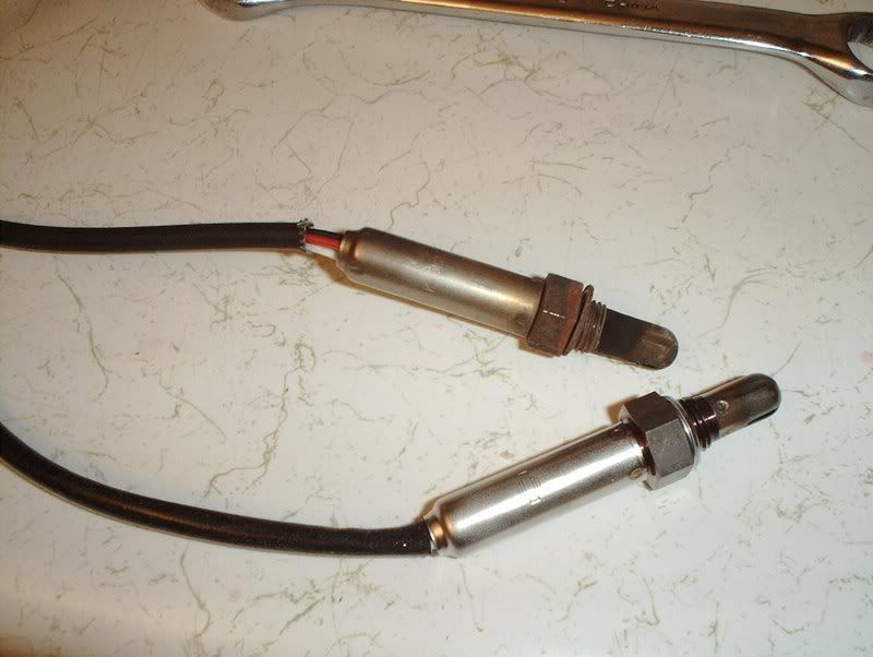
O2 sensor install
Boost controller (no install)
Wire harness (no install)
PAGE 12------------------------------------------
Power steering pump problem SOLVED!!!
Ignition grounding plate install
Water temp gauge install
Coolant/water line replacement under intake manifold
PAGE 13--------------------------------------------
Water temp gauge cont.
Clutch line (no install)
Gauge wiring for Boost/Oil pressure/Water temp
Engine install (no pics)
Steel braided Valvecover T lines install
Intake filter & MAF install
Altima fan fitment modification cont.
Downpipe (no install)
Shifter bushing install
Engine startup
PAGE 14--------------------------------------------
DiF fan controller problem #1
PAGE 15--------------------------------------------
Snap ring problems
Radiator feet part #
PAGE 17--------------------------------------------
DiF fan controller problem FIXED!!!!
***********************************************************
![Image]()
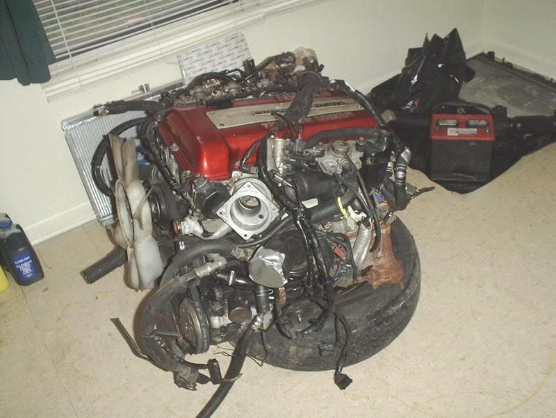
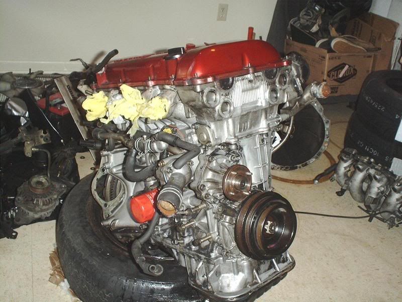
I got my engine in from JSA Motors. Everything was intact, no missing pieces or parts(MAF/Ignitor chip), no broken crank angle sensor and a complete uncut wiring harness. Shipping was swift and I was able to track it to my delivery point. My only complaint was that the block was a little grimey, they said they would clean it before strapping it to the skid.
![Image]()
![Image]()
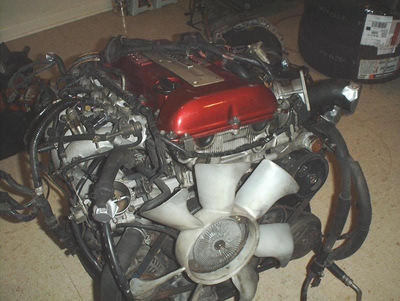
S13 Redtop SR20DET
![Image]()
The transmission is intact and very clean...
![Image]()
no transmission crossmember but I can use my KA's crossmember.
![Image]()
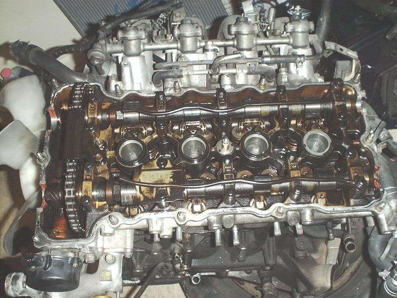
First thing I did was bust open the valve cover and inspect the internals, during my research I read some horror stories about people getting engines with rust and dirt inside.
![Image]()
Apparently someone wasn't too fond of oil changes.
![Image]()
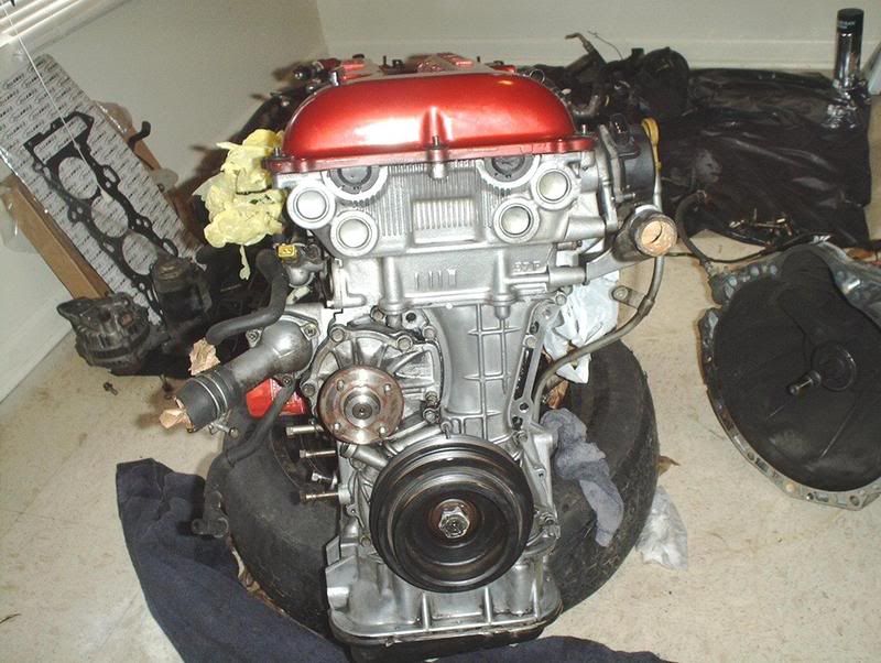
After that I completely broke down the exhaust side of the block. Striped everything!
![Image]()
Did the same for the intake side.
![Image]()
I removed the alternator, P/S pump, A/C compressor and the belt driven fan.
![Image]()
Broke out the bucket O' water, scrub brushes and Mean Green and started scrubbing away but I got tired of killing my back working on this engine on that old tire....
![Image]()
and borrowed a buds engine stand. This thing is a life saver!!!!!!
![Image]()
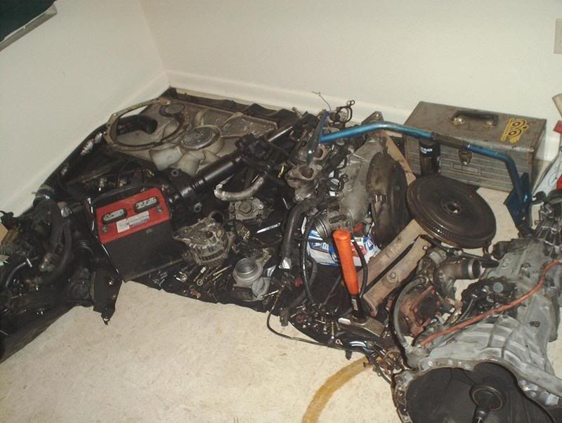
Look at all the stuff I pulled, hope I can remember where everything goes when I try to put it back.
![Image]()
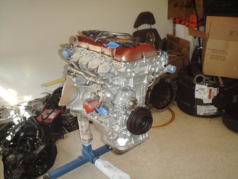
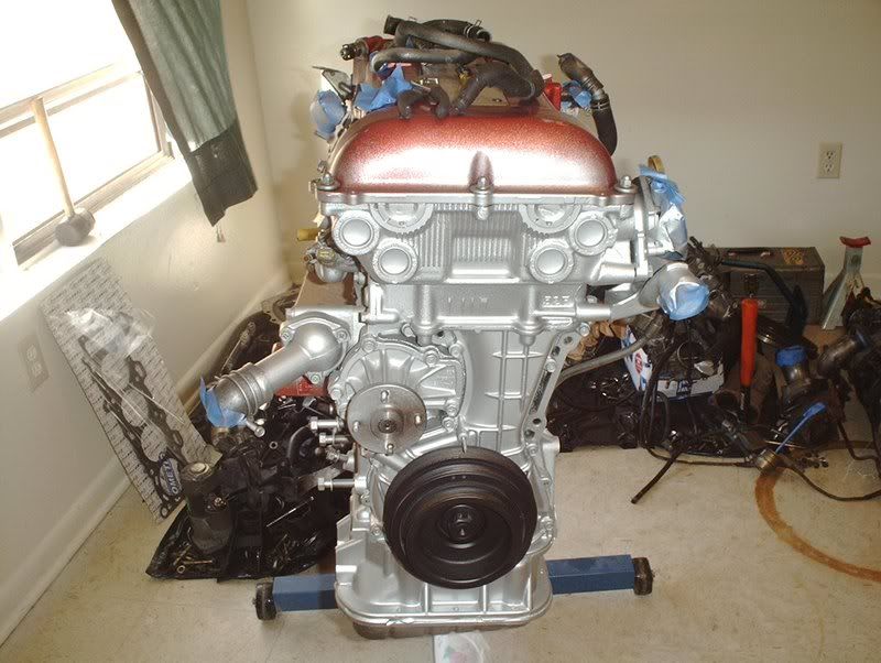
After cleaning every knookie and cranny on this block I taped off everything I didn't want to get coated and laid down a couple of coats of high heat iron cast aluminum engine enamel to the block.
![Image]()
Turned out better that I thought it would.
Now that I had everything cleaned up I turned my attention towards replacing parts. The first parts that I attempted to swap out were the main oil seals. I read up on what should be changed out on any basic engine swap and the oil seals were at the top of the list among other things such as oil pump, water pump, thermostat, spark plugs, various gaskets, motormounts, oil pan, etc.
FRONT OIL SEAL REPLACEMENT
Tools needed:
Socket wrench
Socket extension
27mm socket
Chain
1 transmission bolt
2 flywheel bolts
Pulley puller
Breaker bar
Seal puller or prybar/screwdriver
Seal driver
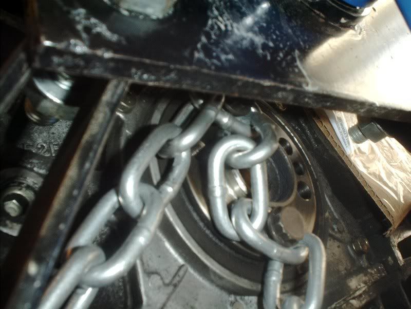
I want to change out the front and rear main seals but I can't get to the rear with the engine on the stand but the front is accesible. To get to it you need to remove the crank pulley but I couldn't get the pulley bolt off because the crank kept spinning when I tried to man up on it and I don't have any air tools so I had to think of another way. I decided to use the chain and the links that I used to pull my KA to help me.
![Image]()
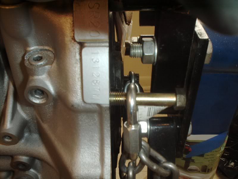
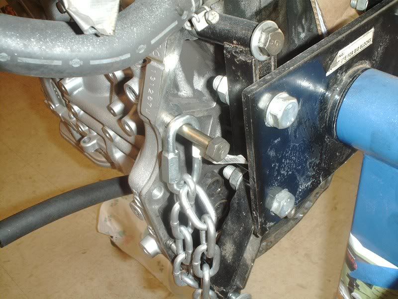
I put two flywheel bolts through the chain and threaded them into the crank.
![Image]()
![Image]()
![Image]()
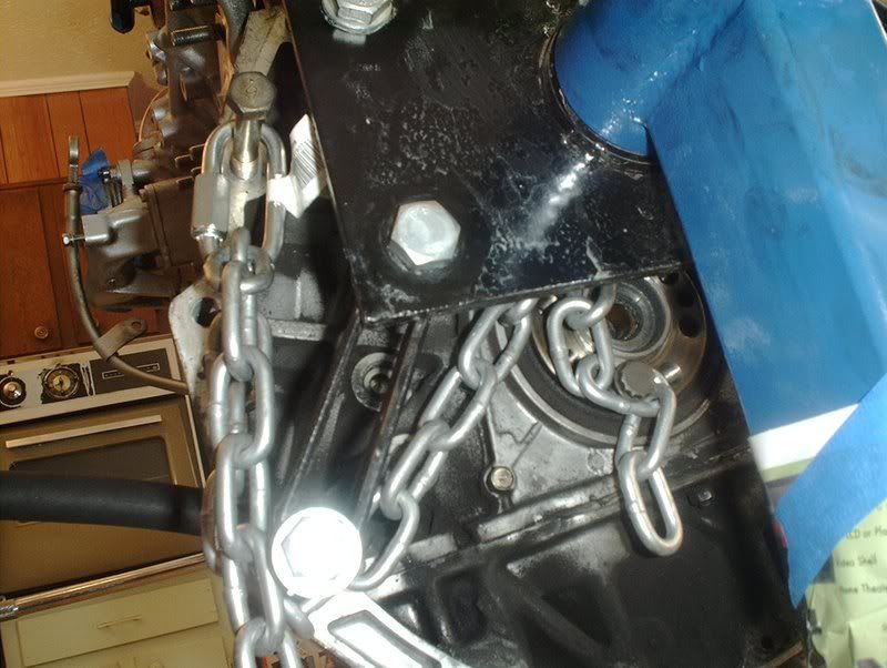
I looped the chain around the engine stand, stuck a transmission bolt into the link and threaded that into the transmission housing.
![Image]()
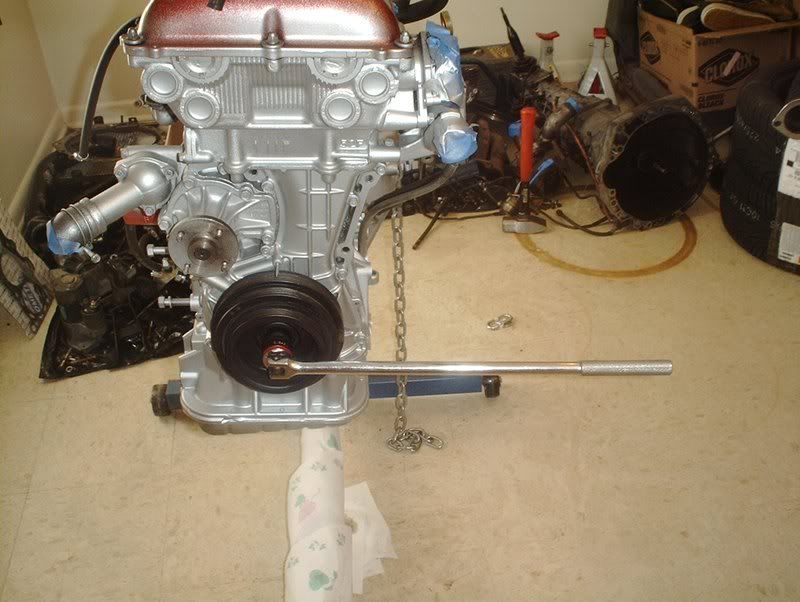
This kept the pulley from spinning.
![Image]()
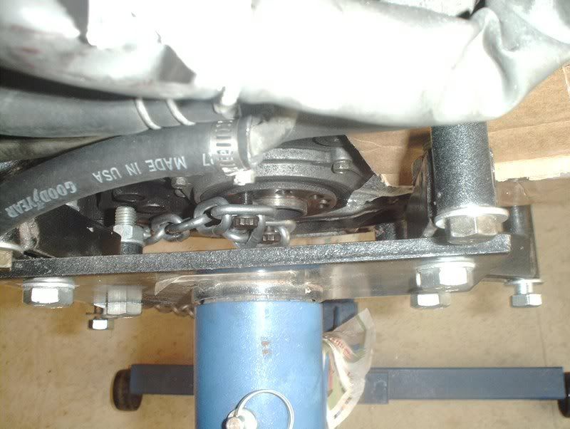
This allowed me to use my 27mm socket and breaker bar to bust the crank pulley bolt loose.
![Image]()
![Image]()
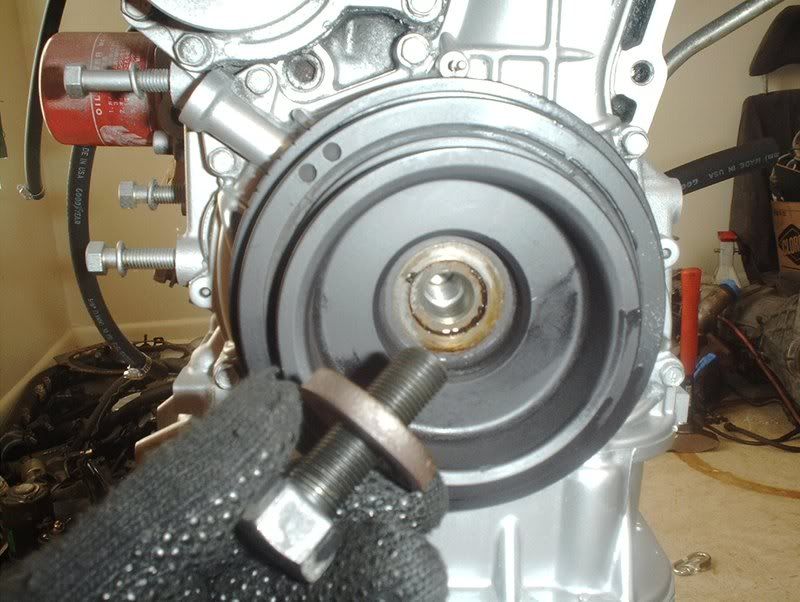
Now I just need to get a pulley puller from the parts store to pop it off so I can replace the front main seal.
![Image]()
Here, you can see the rear main seal that I can't get to yet. Anyone know how it comes out? Does it pry out with a screwdriver or something?
*EDIT**********************************
I decided to put up a quick table of contents for those basic SR swap guys who just need a answer to that one question or just need to see that one pic to verify something.
PAGE 1------------------------------------------------
Introduction and engine breakdown(no pics).
Front oil seal replacement
Intake manifold breakdown
Thermostat replacement
Engine paint
Engine cleaning
Aluminum steering bushing install
PAGE 2------------------------------------------------
Heater hose installation
Engine bay painting
Powersteering pump problem #1
Sidemount intercooler
PAGE 3------------------------------------------------
Water pump installation
Water pump aftermarket pulley installation
Upper and lower radiator hose install
Speed sensor swapout
Intake manifold gasket install
CAS(Crank angel sensor) Replacement
Vacuum hose replacement
Turbo oil return hose install
Dipstick swapout
Fuel injector seal replacement
Fuel regulator install
Oil filter sandwich plate...YOU FAILED EBAY!!!!
PAGE 4-----------------------------------------
Rant Of The Day!!!
Coolant temp sensor replacement
Coolant gauge sensor replacement
Alternator aftermarket pulley install
Vacuum hose install(intake manifold)
Fuel injector seal replacement cont.
Fuel rail install
CAS cover swapout
Turbo breakdown OEM T-25
Turbo gasket install
PAGE 5-----------------------------------------
Water outlet/neck gasket install
Bolt/nut replacement with part #'s
PAGE 6-----------------------------------------
Altima fans vs. Permacool???
Altima fan modifications(get a dremel!!!!)
Altima fan breakdown
Spark plug replacement
Altima fan modification cont.
Altima fan mounting to Koyo rad
Clutch pivot ball problem!!!
Transmission dust collar replacement
Transmission slave cylinder replacement
Wire harness clips part#
Transmission gasket replacement
Power steering pump problem #2
PAGE 7---------------------------------------------
Knock sensor replacement
Transmission gasket cont.
Transmission rear seal
Transmission mount install
Clutch pivot ball install
Clutch pivot fork
Turbo stainless steel line install
Transmission drain plug install
Motor/Engine mount install
Turbo lines install cont.
PAGE 8--------------------------------------------
Turbo manifold/outlet install
Turbo locking nuts install
Turbo manifold gaskets install
Rocker arm install
Transmission insulator mount install
Valvecover part#
Fuel line replacement
Greddy oil pan install
Oil strainer replacement
DiF Fan controller wiring
Valvecover install
Valvecover gaskets install
PAGE 9--------------------------------------------
Turbo manifold install cont.
Flywheel (no install)
DiF fan controller wiring cont.
PAGE 10------------------------------------------
Hotpipe/B.O.V. (no install)
Oil filter relocation kit install
Clutch (no install)
Power steering pump aftermarket pulley install
Power steering pump install problem #3
PAGE 11------------------------------------------
Valvecover install cont.
O2 sensor install
Boost controller (no install)
Wire harness (no install)
PAGE 12------------------------------------------
Power steering pump problem SOLVED!!!
Ignition grounding plate install
Water temp gauge install
Coolant/water line replacement under intake manifold
PAGE 13--------------------------------------------
Water temp gauge cont.
Clutch line (no install)
Gauge wiring for Boost/Oil pressure/Water temp
Engine install (no pics)
Steel braided Valvecover T lines install
Intake filter & MAF install
Altima fan fitment modification cont.
Downpipe (no install)
Shifter bushing install
Engine startup
PAGE 14--------------------------------------------
DiF fan controller problem #1
PAGE 15--------------------------------------------
Snap ring problems
Radiator feet part #
PAGE 17--------------------------------------------
DiF fan controller problem FIXED!!!!
***********************************************************
I got my engine in from JSA Motors. Everything was intact, no missing pieces or parts(MAF/Ignitor chip), no broken crank angle sensor and a complete uncut wiring harness. Shipping was swift and I was able to track it to my delivery point. My only complaint was that the block was a little grimey, they said they would clean it before strapping it to the skid.

S13 Redtop SR20DET

The transmission is intact and very clean...

no transmission crossmember but I can use my KA's crossmember.
First thing I did was bust open the valve cover and inspect the internals, during my research I read some horror stories about people getting engines with rust and dirt inside.

After that I completely broke down the exhaust side of the block. Striped everything!
Did the same for the intake side.
I removed the alternator, P/S pump, A/C compressor and the belt driven fan.

Broke out the bucket O' water, scrub brushes and Mean Green and started scrubbing away but I got tired of killing my back working on this engine on that old tire....

and borrowed a buds engine stand. This thing is a life saver!!!!!!
Look at all the stuff I pulled, hope I can remember where everything goes when I try to put it back.
After cleaning every knookie and cranny on this block I taped off everything I didn't want to get coated and laid down a couple of coats of high heat iron cast aluminum engine enamel to the block.
Turned out better that I thought it would.
Now that I had everything cleaned up I turned my attention towards replacing parts. The first parts that I attempted to swap out were the main oil seals. I read up on what should be changed out on any basic engine swap and the oil seals were at the top of the list among other things such as oil pump, water pump, thermostat, spark plugs, various gaskets, motormounts, oil pan, etc.
FRONT OIL SEAL REPLACEMENT
Tools needed:
Socket wrench
Socket extension
27mm socket
Chain
1 transmission bolt
2 flywheel bolts
Pulley puller
Breaker bar
Seal puller or prybar/screwdriver
Seal driver
I want to change out the front and rear main seals but I can't get to the rear with the engine on the stand but the front is accesible. To get to it you need to remove the crank pulley but I couldn't get the pulley bolt off because the crank kept spinning when I tried to man up on it and I don't have any air tools so I had to think of another way. I decided to use the chain and the links that I used to pull my KA to help me.
I put two flywheel bolts through the chain and threaded them into the crank.
I looped the chain around the engine stand, stuck a transmission bolt into the link and threaded that into the transmission housing.
This kept the pulley from spinning.
This allowed me to use my 27mm socket and breaker bar to bust the crank pulley bolt loose.

Now I just need to get a pulley puller from the parts store to pop it off so I can replace the front main seal.

Here, you can see the rear main seal that I can't get to yet. Anyone know how it comes out? Does it pry out with a screwdriver or something?