
`Shogun´ & +700hkr!
What is Need for Speed...?
A movie? A book? A game?
For me it is a feeling of controling pure, brutal power.
It all started when I had my drivers licence. I built my own dragster, a Cuda -70 with 1136 hp.
It was an awsome adventure to be in control of this extreme machine, knowing I built it myself and have success at the races. Eights on the strip, lovely time it was but rediculously expensive.
Today I¼¶m building an extreme street racer. Handling and brutal power in a nice wraping.
Even if I am building most of it myself, it is costing a lot, but it is worth every single Krona, Euro and Dollar. Luckily there are many good suppliers around the world who produce quality parts at decent prices. I have made many good contacts during the years.
I bought the car in 1998, it was in a very good condition and more important, the engine was flawless and without errors and only a few Miles on it, just to pay.
The first mod I did was 17" rims, lowering springs and adjustable Koni dampers.
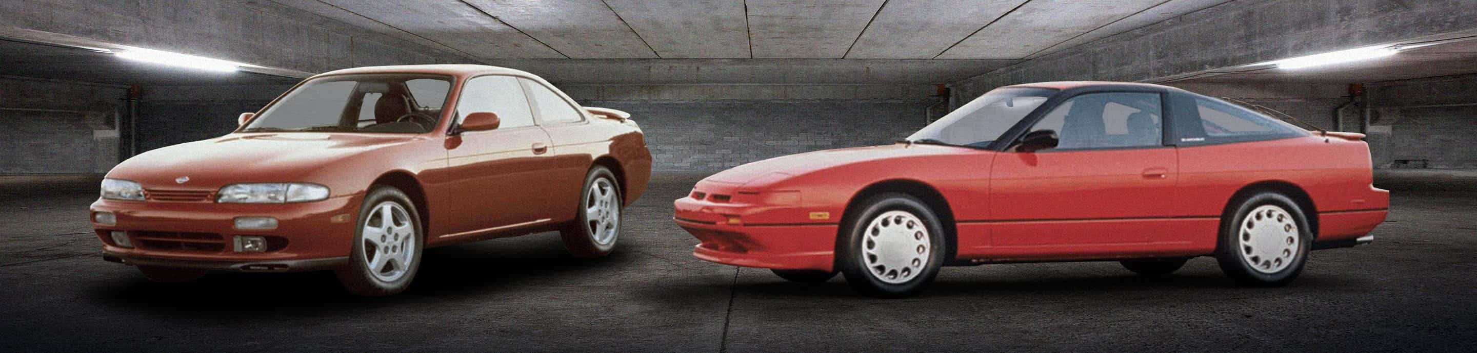
After that some styling. Got in contact with Erebuni and together we found a package and named it Shogun. They still use my car on their site.
The engine needed an upgrade. Started with exhaust system, chip tuning, open air filter and increased boost. The result was rather meager, some lousy 200 hp. Nothing to chear about. I got an intercooler, a larger turbo and a manifold. Increased fuel pressure and a modified chip. Together with some other changes, the engine produced some 300 hp... Still not satisfied.
I sold most of it.
After a heavy research I started collecting high performance parts to make it 100%. Forged pistons, forged rods, new aftermarket control unit, injectors, turbo, manifold, large IC, water cooler, clutch, oil cooler, fuelpressure regulator, blow off valve, etc etc... Bosch Motorsports added high ohm 960cc injectors from their development department. It¼¶s nice to have contacts.
Lots of things is needed to assemble a 600hp engine.
How will the gearbox manage all those horses and the hughe torque?
The original tranny dies between 300 and 400hp...
I have to make my own.
Said and done. I bought a Z32 tranny that without swetting manage more than 1000hp.
The bellhousing was cut off and the S13 flange part was TIG welded on. A special made prop shaft and a tranny bracket was made. Thats it! OK...a short shift on top of it.
Potent engine, durable tranny...but...gripp?
How to solve this?
Bought 18" Japaneese light weight drifting rims and really good rubber.
One of the better LSD:s on the market was bought from ATS in Japan and found its place in the rear axle.
Coilovers, adjustable link/rods made of chrome molly, ball joints, swaybars...there is a long list over all modified chassie parts and upgrades.
I mounted the brakes from a Skyline, both front and rear. The brake discs got some work and the wheel hubs was exchanged to 5-bolt version to prevent the wheels from escaping during acceleration.
The interior was modified with Sparco seats, 3" 6-point belts and some more, making it able to handle and keep full control over engina data and the car handling.
It is not an easy thing to create a monster kind of car but with time and effort it is possible, but not for free. For more information, have a look on my site. There are lots of pictures, both on parts and projects.
I look forward, summer to come
`Shogun¼
![Image]()
![Image]()
![Image]()
![Image]()
![Image]()
![Image]()
![Image]()
![Image]()
![Image]()
![Image]()
![Image]()
![Image]()
![Image]()
What is Need for Speed...?
A movie? A book? A game?
For me it is a feeling of controling pure, brutal power.
It all started when I had my drivers licence. I built my own dragster, a Cuda -70 with 1136 hp.
It was an awsome adventure to be in control of this extreme machine, knowing I built it myself and have success at the races. Eights on the strip, lovely time it was but rediculously expensive.
Today I¼¶m building an extreme street racer. Handling and brutal power in a nice wraping.
Even if I am building most of it myself, it is costing a lot, but it is worth every single Krona, Euro and Dollar. Luckily there are many good suppliers around the world who produce quality parts at decent prices. I have made many good contacts during the years.
I bought the car in 1998, it was in a very good condition and more important, the engine was flawless and without errors and only a few Miles on it, just to pay.
The first mod I did was 17" rims, lowering springs and adjustable Koni dampers.
After that some styling. Got in contact with Erebuni and together we found a package and named it Shogun. They still use my car on their site.
The engine needed an upgrade. Started with exhaust system, chip tuning, open air filter and increased boost. The result was rather meager, some lousy 200 hp. Nothing to chear about. I got an intercooler, a larger turbo and a manifold. Increased fuel pressure and a modified chip. Together with some other changes, the engine produced some 300 hp... Still not satisfied.
I sold most of it.
After a heavy research I started collecting high performance parts to make it 100%. Forged pistons, forged rods, new aftermarket control unit, injectors, turbo, manifold, large IC, water cooler, clutch, oil cooler, fuelpressure regulator, blow off valve, etc etc... Bosch Motorsports added high ohm 960cc injectors from their development department. It¼¶s nice to have contacts.
Lots of things is needed to assemble a 600hp engine.
How will the gearbox manage all those horses and the hughe torque?
The original tranny dies between 300 and 400hp...
I have to make my own.
Said and done. I bought a Z32 tranny that without swetting manage more than 1000hp.
The bellhousing was cut off and the S13 flange part was TIG welded on. A special made prop shaft and a tranny bracket was made. Thats it! OK...a short shift on top of it.
Potent engine, durable tranny...but...gripp?
How to solve this?
Bought 18" Japaneese light weight drifting rims and really good rubber.
One of the better LSD:s on the market was bought from ATS in Japan and found its place in the rear axle.
Coilovers, adjustable link/rods made of chrome molly, ball joints, swaybars...there is a long list over all modified chassie parts and upgrades.
I mounted the brakes from a Skyline, both front and rear. The brake discs got some work and the wheel hubs was exchanged to 5-bolt version to prevent the wheels from escaping during acceleration.
The interior was modified with Sparco seats, 3" 6-point belts and some more, making it able to handle and keep full control over engina data and the car handling.
It is not an easy thing to create a monster kind of car but with time and effort it is possible, but not for free. For more information, have a look on my site. There are lots of pictures, both on parts and projects.
I look forward, summer to come
`Shogun¼


