Introduction
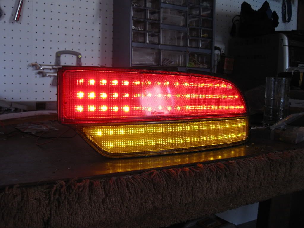
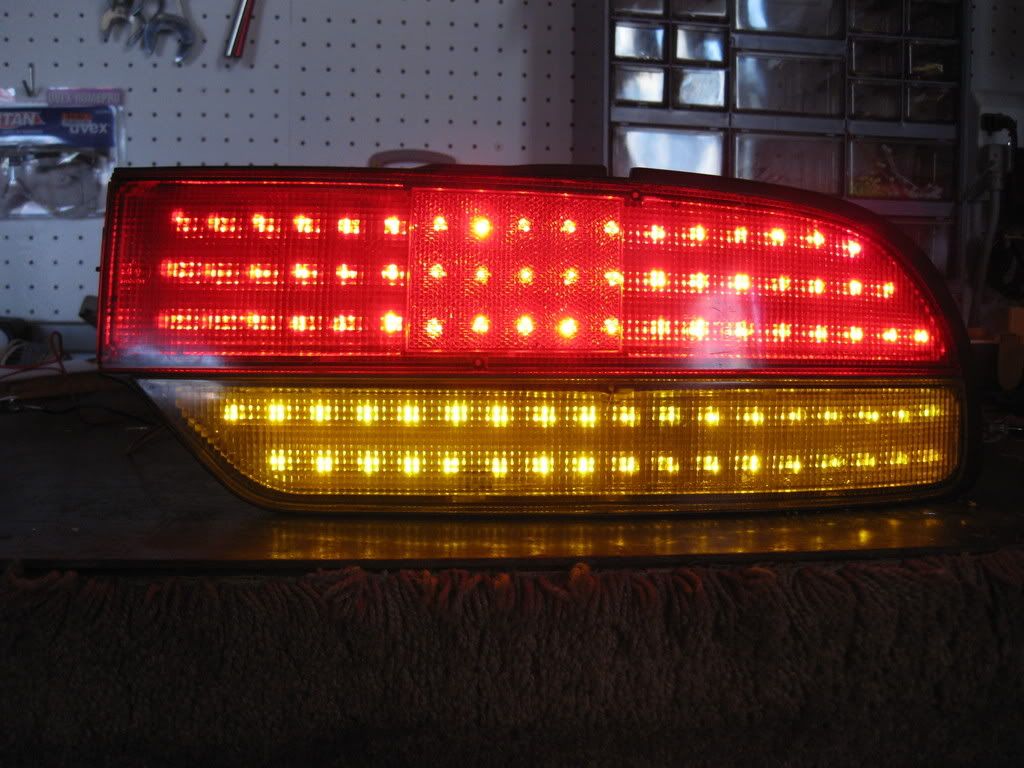
I've always been inspired by the aesthetic artistry of cars. As such I tend to obsess on the exterior modifications, always searching for a balance between something that is sleek and and catchy without being gaudy or ricey. I've seen several led replacement lenses come out for the S14, and just recently people have started to modify the s13 coupe tail lenses. However there's been little love for our S13s in the LED department apart from some questionable ebay kouki knockoffs. Anyway I was inspired by some of the other LED projects that have been posted up here in the forums, and since my s13 is 400 miles away, I decided I'd pass some time and retrofit a spare set of tails with LEDs.
So, if you liked the results of my project as seen in videos above, please feel to use this DIY to create a set for yourself.....
Disclaimer!
1. While I've managed to create working LED tail lights I've been unable to mount them, and therefore I
a) don't know how they'll fare in extreme weather (more on this later, I have some ideas and suggestions to improve durability)
b) don't know how your local police will react to the modification. Technically you're still using the oem housing, but the LEDs are super bright and may attract attention
2. Again my s13 is parked in Vegas until such a time as I can afford to tow it out to Cali, so please don't ask me for mounted pics of the lights. Perhaps another community
member will complete this project and oblige us with mounted pics
3. This project is not for beginners. It took me a long time to learn what I needed to know to put these lights together. If you're not familiar with LEDs I'd suggest starting
with simpler modifications like dome light conversions, or even better, convert your third brake light first as it will compliment your completed tails.
4. I will be using many pics and very large ones at that to clearly demonstrate what you need to do, so don't complain about pic size!
5. This project will take you a considerable amount of time. I highly recommend you purchase a spare set of tail lights to modify if your s13 is your DD. Furthermore a spare
set of tails is desirable in the event you crack a lens during the baking process.
6. Take your time, work slowly, and follow the instructions. I broke alot of stuff and fluxed out a lot of LEDs doing the trial and error so you wouldn''t have to!
7. I spent alot of my free time making these, and I'm spending even more of it writing this DIY by popular request. If you have a suggestion or criticism, keep it positive and
beneficial to the community.
Materials Needed
Driver and Passenger fastback Tail Lights
108 red leds (5mm 8000mcd)
72 yellow/amber leds (5mm 5000-8000mcd will do for brightness)
72 470ohm resistors 1/4 watt (if you ebay your leds from china they'll usually supply you with free leds, just specify which type you need)
36 1.5k resistors 1/4 watt
4 220 ohm resistors 1/4 watt (1/8 watt resistors will also work the same, for our project. You'll see my 470s are 1/8 while the others are the larger 1/4)
*special note, you should buy extra components in case you damage any leds soldering etc etc. I recommend that you buy 150 red 100 yellow 100 470ohm 50 1.5kohm and 10 220ohm.
Electrical solder 1-2 tubes depending on your soldering habits
PCB board (to make led pattern template) copper rings not necessary
Glue gun sticks
Electrical wires
Electrical tape
Tools Needed
- Basic Screwdrivers
- Oven
- Gloves/Oven mitt
- Fine point mechanical pencil
- Scissors
- Paper/cardboard
- Thumbtack
- Scotch tape
- Dremel tool with very fine drill bits (unsure of exact size, but small enough to drill through the holes created by a thumbtack prick)
- Larger drill bits approximate size of your 5mm led
- Hot glue gun
- Soldering Iron
- needle nose pliers
- plier snips
- Voltometer (a simple digital one will do)
- test wires/alligator clips
Step 1: Bake the lenses
To bake the lenses you'll first need to remove 8 screws from the back portion of the light. They are holding the lens to the casing. Screw positions are noted in this picture:
Next you'll want to heat your oven to between 225 degrees and 240 degrees. Place the lenses in the oven on a cookie sheet or something similar and let them warm up for approximately 13-15 minutes to loosen up the rubber glue holding them together.
Next put on your gloves, and GENTLY use a small flathead screwdriver to work around each lens to work it free from the housing. Try not to torque too much as the more you crank on the lips of the housing, the more bent they will be when you go to put everything back together. For the most part everything goes back into original shape, but I noticed some spots where the lip was not flush by a couple millimeters. Not a huge deal aesthetically, but you don't really want to give water a chance to get inside your lenses later on.
Continue working the lenses free, and alternate between pushing from the inside of the housing, and working the lens loose on the outside. I personally found it easiest to work the amber lens out first, then work out the red lens.
*special note! While the lenses should be somewhat difficult to get out, you should not be having to apply too much excessive force. If you're really cranking on the lenses, then the glue isn't warm enough!
It takes a couple minutes to work everything out. If you notice the glue starting to get unfriendly, just stick everything back in the oven for another minute or so. Again resist the temptation to crank the lenses out of the housing by torking on them with the screwdriver. I cracked my first lens during removal. Beware of these weak points where the lenses are most likely to crack during removal.
Again the best method is to lightly work the lenses out around the edges with the screwdriver, while putting most force on the lense from behind. Just push on the reflector housing inside and it will push the lens straight out from the main housing. If you've heated the glue up properly everything should slide out easily. Remember, if you're forcing the lens, you're not doing it right.
Sorry to beat a dead horse so much here, but trust me, you'll hate yourself if you crack one of your lenses.
Step 2: Preparing your LED board
One of the benefits of my design is it will save you a bit of money in the pcb board department. As I was unable to find enough pcb board to fill up both of the tails for a reasonable price, I decided simply to convert the reflector housing into my LED board, and it worked out quite nicely I think. Here's what you need to do
1st - trace out the basic shape of your reflector housing and cut it to shape until it fits inside the housing as shown in the pic.
.
2nd - Since you don't need to drill all the holes in a standard electrical pcb board, you just need to determine which ones will be occupied by your leds and transfer the design to your template. You'll need just one piece of electrical pcb board to do this.
My design for the Brake light uses vertical rows of 3x17 horizontal with an additional two rows that taper off to fill the corners. Therfore one brake light will require 54 red leds if you follow my design exactly. I achieved this count by making exact grids by overlaying my pcb test board with scotch tape, leaving only the holes open that would be occupied by my leds. The pictures will show what I'm explaining:
If you'll look closely, you'll see that the scotch tape perfectly laid out masks off 7 little holes, and when it's laid out in cross sections you're able to quickly mask off 7x7hole sections. As you work horizontally, you just need to leave one free row of holes between rows of tape. Vertically you'll leave two rows between tape sections. This will give you a nice perfectly spaced led grid.
Next lay your marked off pcb board over your templates you just cut out, line them up to where you want the leds to sit, and mark the holes with a fine mechanical pencil.
You can use the same masked pcb board for both the blinkers and brake portions of the tails. Just use two vertical rows only for the blinkers, while making three rows for the brakes. Furthermore, you don't need your pcb board to cover the entire length of the tail, it's sufficient to simply mark the drill points, and just shuffle the board down the length of your paper template. Just make sure the holes all line up. It's pretty simple stuff really.
From here you have two choices, you can use this paper as your drilling template. I personally chose to make something more durable in the event I wanted to create more of these, and also to facilitate easier drilling. So what I did was cut out a thin cardboard template to match the paper template. Scotch tape the two together, and use a thumbtack to punch through all the holes you just marked. ( you could possibly skip this step and just drill through the holes later, it's up to you) I personally did everything the long way as I wanted to ensure getting a perfectly straight end result.
Your end result should be some nifty drill guides that look something like this:
Now comes the fun part, drilling. Scotch tape your cardboard templates to the back of the reflector housings. Make sure everything is lined up the way you want it, and then drill away. You're going to need a dremel with a very tiny drill bit to do this!
and....TADA! you're very own custom pcb board, that magically will fit perfectly back into the tail light housing when you're all done:
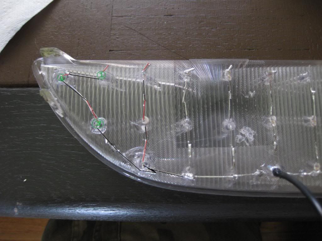
Take note of where the corners of the housing taper off, You'll need to drill out and hollow these mounting points so that the led will be recessed back into the reflector housing, otherwise it will come in contact with the exterior lens upon reassembly.


")